Bipolar Thyristor

Bipolar Thyristor

Bipolar Thyristor

Bipolar Thyristor

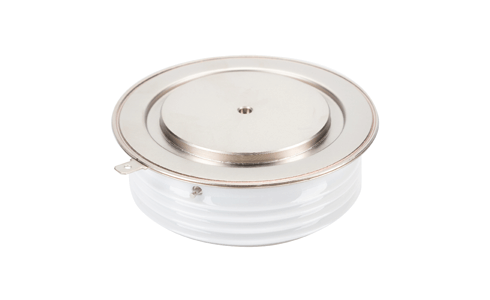
Dynex Thyristor Discrete devices range from 1.3kV to 8.5kV with currents up to 6650A and work reliably at line frequencies from -40°C to 125°C.

IGBT Product

Dynex Bipolar Thyristor


Dynex design and manufacture Thyristor Discrete devices tailored for particular applications with lower losses, higher blocking voltages and increased current capability.

Phase Control Thyristors


The Dynex Phase Control Thyristors range from 1200V used with domestic supplies, to 8500V for medium voltage applications. High overload capability ensures the thyristors are suitable for fuseless applications.

Operating at line frequencies where switching losses are small, the low conduction losses of Phase Control Thyristors increase system efficiency.

Phase Control

Phase Control Thyristors Details

The Thyristors can be used in applications that require efficient energy, switching at line frequencies without turn-off capabilities such as power grid and renewable energy.

Dynex Thyristors are typically used in AC to DC converters (Rectifiers) which employ phase control to vary the average voltage on the output of the converter or to switch the AC supply on and off. Operating at line frequencies where switching losses are small, the low conduction losses of phase Control Thyristors enable increased system efficiency.

Designs are tailored for particular applications with lower losses, higher blocking voltages and higher current capability.

Phase Control

Phase Control Thyristor Features

  • Current ratings from 370A to 7610A
  • Full blocking voltage capability at line frequencies from -40°C to + 125°C
  • High surge current capability
  • High di/dt turn-on capability
  • High DC blocking stability
  • Low conduction losses
  • Low thermal resistance
  • Excellent pick up performance for parallel operation

Pulse Power Thyristors


Dynex manufacture a range of Pulsed Power thyristors for extremely fast turn-on based on its Gate Turn-Off (GTO) structures. The devices have been designed at 3300V and 4500V at current ratings of 493A to 1670A. The structures are resistant to cosmic ray induced failures at normal working voltages.

Pulse Power Thyristors are designed for extremely high di/dt switching and fast turn-on in combination with a high current capability and high voltages, they can also include special driver units.

Pulse Power Thyristors

Pulse Power Thyristors Details

Dynex Pulse Power Thyristors (PPTs) are based on Dynex’s GTO technology and are designed for long-term stability under DC voltages. The structures are resistant to cosmic ray induced failures at normal working voltages.

The range may be used to connect a source of stored energy such as a capacitor to a load, or to bypass and protect the load in the case of a crowbar circuit. In pulsed power applications where the rate of current is very fast, the pulsed power switch acts as a closing switch and standard phase control thyristors (SCRs) are likely to fail due to the high di/dt experienced.

Pulse Power Thyristors

Pulse Power Thyristors Features

  • Single or repetitive pulse applications
  • Very highly interdigitated gate structure
  • Very high di/dt capability
  • Fully floating silicon technology
  • High “shot life”
  • High reliability / life compares to vacuum tubes
  • Designed as a closing switch

Asymmetric Bypass Thyristors


Dynex Bypass Thyristors are designed at 3300V and 4500V with current ratings of 2900A and 3200A. The thyristors feature dynamic on-state voltage with overall turn-on time to determine the current diversion from the IGBT diode.

The primary characteristics of the bypass thyristors are dynamic on-state voltage which determines current diversion from the IGBT diode and overall turn-on time.

Asymmetric Bypass Thyristors

Asymmetric Bypass Thyristors Details

Dynex Bypass Thyristor are designed for the protection of IGBT modules in VSC multi-level applications, where a reduced forward blocking voltage is required.

The design of the bypass thyristor provides greater flexibility to the system designer, allowing compactness, better reliability and facilitating a push towards higher scheme voltages.

They are resistant to fast voltage transients, which can be exposed due to the switching of the IGBT diode. The device structures have greater enhanced hardness to cosmic ray induced failures, which become significant at high DC voltage duty cycles.

Asymmetric Bypass Thyristors

Asymmetric Bypass Thyristors Features

  • Low dynamic on-state voltage for high-performance fault protection
  • Double side cooling
  • Enhanced surge rating
  • High dV/dt capability >10kV/μs
  • High di/dt capability
  • Device can be switched from low anode-cathode voltage
  • FIT rating is orders of magnitude lower than its IGBT companion

Bipolar Thyristor Frequently Asked Questions

What size of snubber circuit design should I use and what are the tradeoffs I need to consider?

Please refer to our Application Notes AN6175 for technical guidance

When might I consider to apply a bipolar based solution?

You should consider the electrical operational conditions for your product such as switching frequency, rail voltages, power dissipation and the likely occurrence of over specification excursions (see AN5948) as bipolar products are robust and more likely to withstand these without failure. The cost and difficulty of service team visits or contractual penalties for non-operation should be considered if applicable. Bipolar devices housed in ‘hockey puck style packages’ are all hermetic devices.

Why is there such a broad range of Qrr (stored charge) and VF (forward voltage drop)?

Dynex ‘s Bipolar datasheets show the full range of Qrr & Vf possible, but you would normally want to enhance. Typically, when evaluating Qrr and VF, the maximum Qrr and minimum VF or the minimum Qrr and maximum VF should be considered in tandem. Once you have defined your system specification you should consult with your local Dynex contact to agree the required Qrr & Vf values for your design.

What makes a Dynex Gate Turn-off Thyristor so reliable?

Dynex Gate Turn-off Thyristors have a track record for reliability and performance in demanding operational environments such as railway traction. This is achieved by including a frequency test step that screens out potential infant mortality.

How does a gate turn-off thyristor (GTO) work?

A gate turn-off thyristor (GTO) is a high-power semiconductor device. It works by acting as a switch in high voltage circuits. Like a thyristor (SCR Silicon-Controlled Rectifier) it has 3 terminals; anode, cathode and a gate terminal. Both a GTO and SCR have a controlled turn on function via the application of a  positive pulse to the gate terminal, but the GTO also has controlled turn-off function by the application of a negative pulse to the gate terminal. An SCR only turns off when the forward current drops below the threshold holding current  The turn-off time is typically more than 10 times faster than for an SCR (silicon-controlled rectifier) thyristor.

What features can I expect from Bipolar Thyristor devices?

  • Thinner silicon, 
  • Lower conduction losses,
  • Unique bevel maximises current and surge ratings,
  • Advanced implanted aluminium diffusion techniques,
  • Full blocking voltage capability at line frequencies from -40°C to +125°C,
  • Double side cooling,
  • High surge current capability,
  • Fault protection,
  • Double side cooling,
  • Low losses for high efficiency,
  • Low thermal resistance

Dynex has an established Bipolar engineering design team and a complete in-house manufacturing production line, from wafer fabrication through to testing. The thyristor devices are tailored for a broad range of applications and provide low losses, high blocking voltages and high current capability.

What are the key features of the i2 Thyristor range of products?

Dynex's i2 Phase Control Thyristors with options ranging between 4200V - 8500V offers:

  • thinner silicon with low conduction losses 
  • utilises 100% of the blocking capability of the silicon
  • the unique bevel maximises the current and surge ratings by increasing the contact area
  • exclusive aluminium diffusion techniques allow us to fine tune the diffusion profile making the i2 Thyristors more robust and reliable
     

What is the difference between a Silicon Controlled Rectifier (SCR) and a Thyristor?

A Thyristor is a broad category of semiconductor devices with similar characteristics including SCR's and GTO's. Whereas a SCR is a specific type of Thyristor. 

Each type of thyristor has its own unique characteristics and applications, however they all share the fundamental ability to control the flow of electrical current through them.

A SCR is primarily used as a one directional switch conducting current from an anode to cathode. Used in applications where there is a need to control DC power such as in high-voltage applications. Phase Controlled Thyristors are also known as phase-controlled rectifiers or SCR's and are used to provide phase-controlled rectification. They are used in motor drives and power supply applications.

Gate Turn-off Thyristors are used in various applications where precise control of high electrical power levels is required such as in HVDC transmission systems to convert AC to DC current for efficient long distance power transmission and back again for distribution.

The main difference, therefore lies in their control characteristics.

Will Dynex help with customised Thyristors for specific application requirements?

DYNEX are able to design customer specific Thyristors based on existing technology platform to achieve specific requirements:

  • Lead type 
  • Lead length  
  • Bespoke Printing 
  • Custom Test specs 
  • Parameter matching: Series (Qrr matching), Parallel (Vtm matching)
We are actively expanding our Bipolar wafer fab capacity to address increasing customer demand. 

Our Applications


Talk to us

If you need to talk to us about any of our products or services, get in touch.

+44 (0)1522 502 901

Quick Enquiry